• Analog vs. Digital Signals: What Changes in Transmission via Slip Ring?

    Analog vs. Digital Signals: What Changes in Transmission via Slip Ring?

    Data transmission via slip ring in Industry 4.0

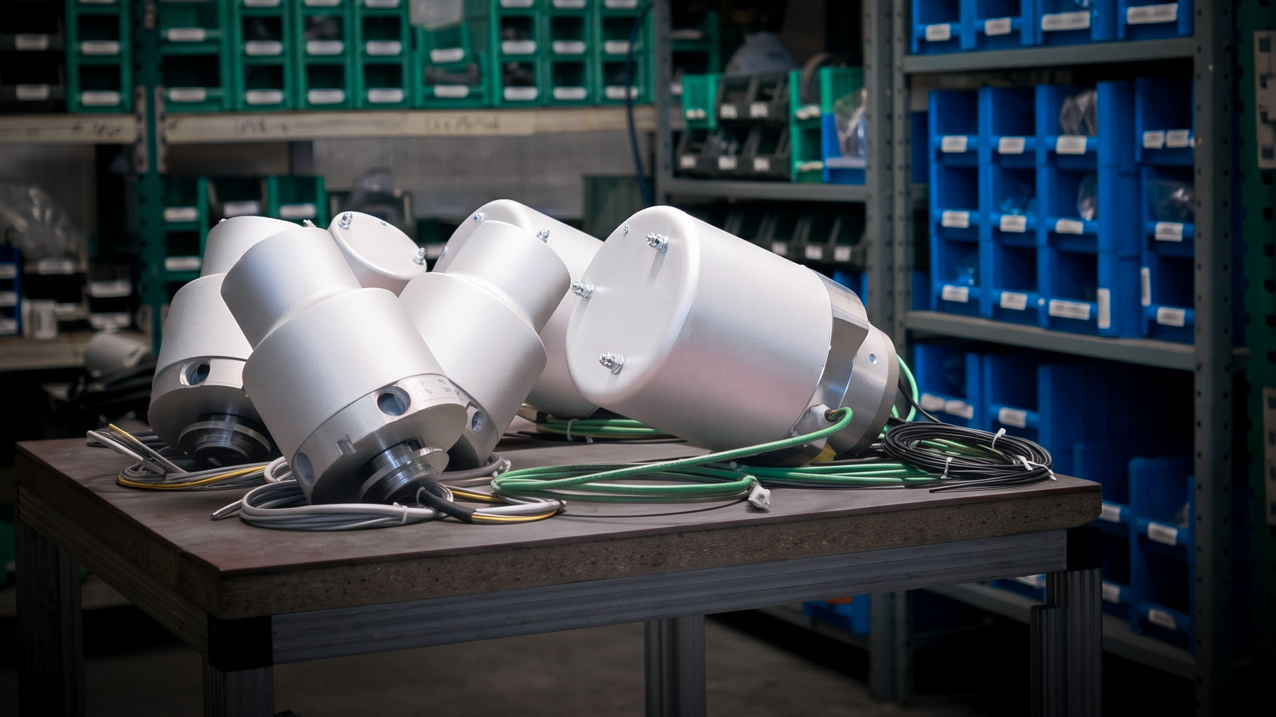
    Sensors, motors, servo drives, and control systems need to exchange information even when located on continuously rotating parts. Data transmission via slip ring allows connecting these devices from the stationary part of the machine to the rotating one, avoiding cable twisting. In Industry 4.0, a slip ring can be required to handle analog measurements and digital communications, such as CAN bus or industrial Ethernet networks, including Profinet, Profibus, EtherCAT, and EtherNet/IP. Each connection has specific requirements: electrical continuity is essential, but it is also necessary to preserve signal quality during rotation.

    Analog, digital, and power signals: different needs

    An analog signal represents a physical quantity through a continuous value, for example, a 0–10 V voltage or a 4–20 mA current. Superimposed noise can alter the measurement, where noise is defined as an unwanted electrical disturbance that superimposes on the useful signal, modifying its voltage or current. In a machine, this can be generated, for instance, by motors, inverters, or electrical switching. Inside the slip ring, even small variations in the contact between brushes and rings can contribute to signal perturbation. The effect of cable and contact resistance, on the other hand, depends on the circuit. 4–20 mA connections are generally less sensitive to resistive drops compared to voltage signals, provided the power supply maintains the necessary operating margin. Digital signals encode information into discrete states and tolerate a certain amount of noise. However, if the receiver’s margins are exceeded, communication errors can occur. Therefore, there is no absolute superiority of analog or digital: what matters is the interface, the speed, and the operating environment. Power circuits have a distinct function, which is to feed loads, and require close attention to current, voltage drops, and heating.

    Electrical noise and crosstalk: why the path matters

    During rotation, variations in contact resistance can introduce disturbances. Added to these are interferences from nearby motors, inverters, and circuits. Crosstalk is the unwanted coupling through which one circuit disturbs another. In high-speed digital connections up to 100 Mbps, like Ethernet, impedance, attenuation, and signal reflections also become critical. The slip ring must therefore be evaluated as part of the entire connection, along with cables and connectors. Circuit layout, maintaining twisted pairs, and properly connected shielding all contribute to preserving communication integrity.

    The Celco approach: custom contacts and configuration

    Celco markets standard slip rings and also develops custom ones based on currents, signal types, rotation speeds, and environmental conditions. This analysis allows us to define a solution that is perfectly consistent with the machinery and the connections to be established. When choosing contact technology, pairings like gold-on-gold can facilitate low electrical noise; silver-based solutions must be evaluated according to the load and operating conditions. The choice must be completed with wiring suitable for the protocol and an internal layout that minimizes the coupling between power and data. Materials, cables, and shielding for the specific configuration must be agreed upon with the technical department: the contact metal alone does not determine compatibility with an industrial network.

    Do you need a hybrid slip ring for power and signals?

    A hybrid power and signal slip ring allows you to combine power supply and communication within the same rotary assembly. To define it correctly, you need to specify voltages and currents, number of circuits, signal type, protocol, transmission speed, and cable length, in addition to mechanical and environmental constraints. Contact Celco’s technicians to evaluate your project. Sharing these data right from the early stages allows us to identify the right configuration and the necessary verifications to seamlessly integrate the slip ring into your automation system.
  • When and How to Inspect an Industrial Slip Ring, if Inspectable?

    When and How to Inspect an Industrial Slip Ring, if Inspectable?

    Preventive Maintenance of Slip Rings: Reducing Unexpected Downtime

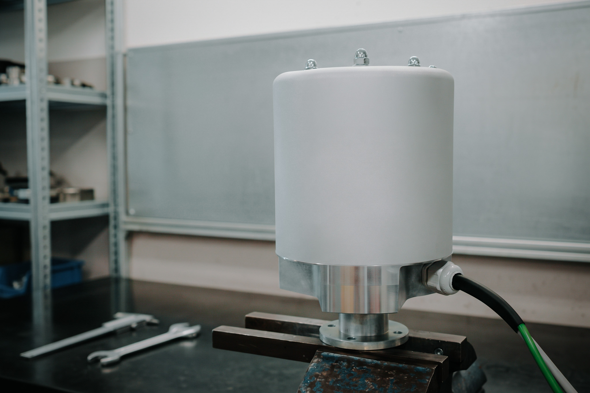
    A rotary electrical slip ring transfers power and signals between stationary and rotating parts. The optimal continuity of this connection contributes to the proper functioning of the machine: wear, contamination, or contact anomalies can compromise power supply and communication. Preventive maintenance of slip rings helps identify problems before they cause an unexpected shutdown. Inspection intervals depend on the model, service hours, speed, and operating environment. The baseline reference is the manufacturer’s maintenance schedule, which should be supplemented by observations gathered during use.

    Sealed and Inspectable Slip Rings: When Can They Be Opened?

    Before intervening, it is necessary to identify the type of component. For slip rings declared “maintenance-free,” the user is not normally required to perform periodic operations on the internal contacts. However, the external checks indicated by the manufacturer remain necessary, such as inspecting fastenings, cables, and enclosure integrity. “Sealed” and “maintenance-free” are not synonymous: a protected enclosure may provide access for servicing. Conversely, the presence of screws does not automatically authorize disassembly. For inspectable models, opening must exclusively follow the manual and be performed by qualified personnel while the machine is stopped, energy sources are isolated, the absence of voltage is verified, and restarts are prevented (locked out).

    What Warning Signs Should Be Monitored?

    Measurement fluctuations, intermittent interruptions, and new communication errors deserve attention, especially when they repeat at specific positions or rotation speeds. Unusual noises, vibrations, anomalous temperature increases, or overheating odors also require verification. These symptoms do not automatically prove a slip ring failure: the root cause may also lie in wiring, connectors, alignment, or connected devices. Recording when the anomaly appears, along with the speed, load, and operating hours, aids in the diagnosis. Signs of burning or overheating require a safe shutdown and a technical evaluation before resuming service.

    Inspection and Cleaning: Protecting Brushes and Rings

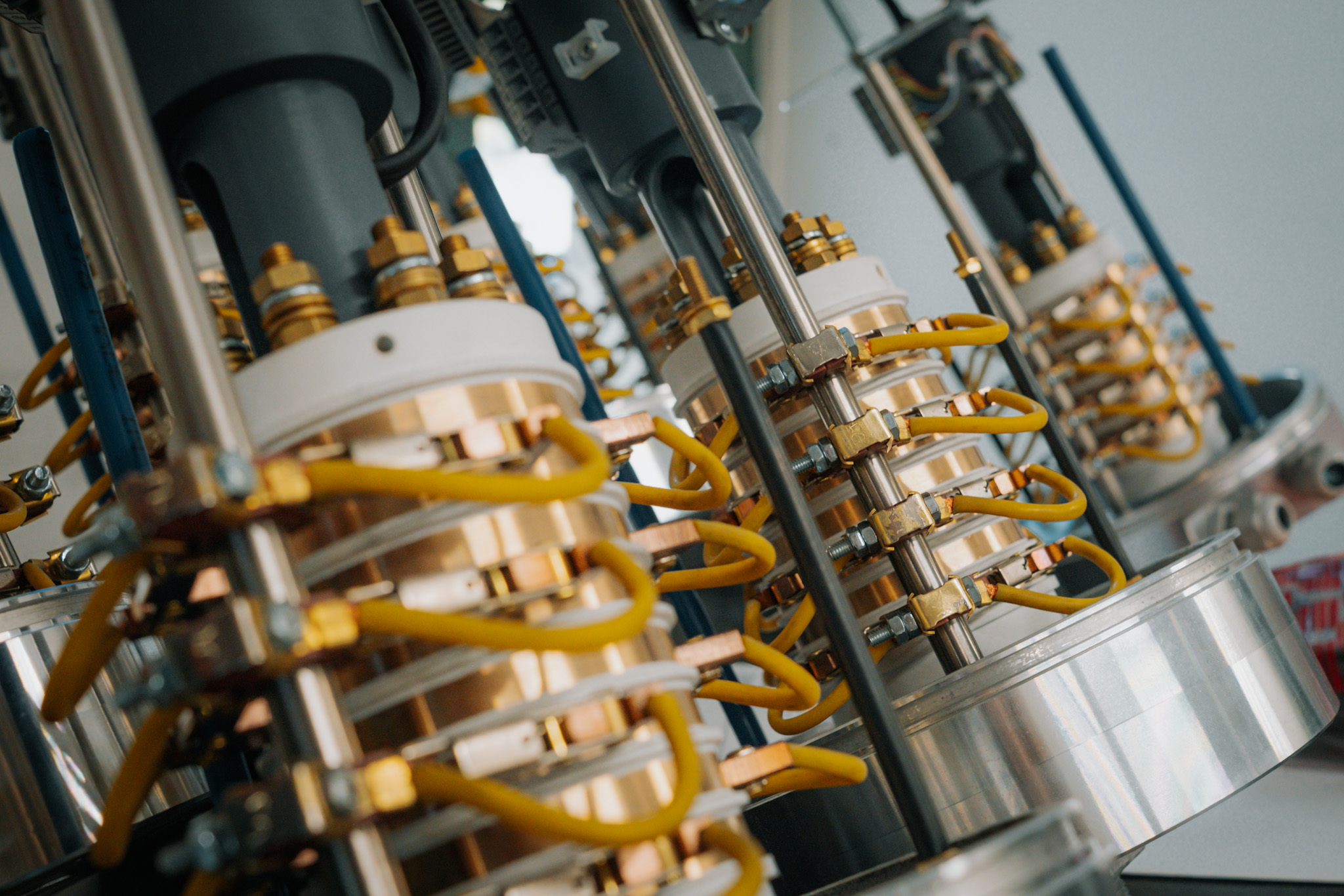
    When the manual permits internal inspection, checks should focus on residue accumulation, brush wear against prescribed limits, and the condition of the rings, connections, and insulators. Grooves, irregular deposits, or traces of overheating must be reported. Conversely, a uniform patina on the rings can be normal for certain technologies and should not be removed indiscriminately. The dust generated by wear can be conductive. Where specified by the manual, it must be removed by vacuuming (not blowing) using suitable equipment, carefully avoiding impacts on the rings and contacts. Do not use compressed air, abrasives, solvents, or lubricants without explicit instruction: they can scatter residues, damage surfaces, or alter the device’s operation. The correct procedure always depends on the specific model in use.

    Celco Design and Maintenance Manual

    The lifespan between one intervention and the next is built directly into the design phase. Celco Profil develops its solutions by considering currents, signals, speeds, and environmental conditions—parameters that guide the selection of the slip ring and help limit stress and wear in the intended application. To determine when to open the component, which checks to perform, and how to clean it, you must follow the instructions for your specific configuration. Request the updated use and maintenance manual from Celco, providing the model, serial number (if available), and operating conditions. This will allow you to schedule interventions precisely according to the guidelines provided for your slip ring.

  • Protection Ratings Explained in Rotating Systems

    Protection Ratings Explained in Rotating Systems
    What Does the IP Rating Mean in Rotating Systems?

    Processing dust, splashes, and washdowns can put electrical slip rings to the test. To choose a suitable component for an industrial environment, a fundamental reference is the IP protection rating, defined by the IEC 60529 standard.

    The code describes the protection provided by the enclosure: the first digit relates to access to hazardous parts and the ingress of solid foreign objects, including dust; the second digit relates to the harmful effects of water ingress. It is a classification tied to specific test conditions: on its own, it does not indicate resistance to detergents, corrosion, or any high-pressure jets.

    IP54, IP65, and IP67: What Are the Differences?

    For industrial slip rings, distinguishing between the different levels helps in formulating the technical request correctly.

    IP RatingDust ProtectionWater Protection
    IP54Ingress is not entirely prevented, but it must not compromise operation or safety.Splashes of water from any direction.
    IP65No dust ingress under test conditions.Water jets under the conditions specified by the test.
    IP67No dust ingress under test conditions.Temporary immersion according to defined depth and duration.

    These conditions describe different types of exposure. A component designed to withstand splashes has different requirements compared to one subjected to temporary immersion. Furthermore, IP65 does not equate to suitability for pressure washing: pressure, temperature, and jet distance must be specifically evaluated.

    Why Does Rotation Make Sealing More Complex?

    In a static joint, the seal operates between stationary, stabilized surfaces. In a rotating system, however, the seal must contend with relative movement, friction, wear, and heat. Misalignments and surface conditions further influence the system’s behavior.

    The choice must therefore consider speed, the diameter of the contact surface, temperature, and service life. At the same revolutions per minute (RPM), a larger diameter results in a higher peripheral speed. The design must balance protection, friction, and durability: increasing the contact pressure of the seal might improve certain aspects of sealing but can also generate more heat and wear.

    Seal Design at Celco

    For a custom slip ring, the starting point is the real-world environment of the machine. During discussions with Celco’s technical department, it is essential to define the present contaminants, washdown methods, rotation speed, and exposure times.

    Solutions to evaluate include O-rings for static joints, dedicated seals for dynamic interfaces, and labyrinths, which obstruct the path of contaminants. While O-rings are sealing elements, labyrinths are structural geometries. The choice of seal materials also depends on temperature and compatibility with the substances present.

    The goal is to identify a configuration suited to the specific application. The declared IP rating must always be read alongside operational limits: high speeds and prolonged exposures require specific design verifications.

    How to Identify the Correct IP Rating for Your Machine

    Before making a choice, describe how the slip ring will be exposed to dust and water, whether it will rotate during exposure, and what conditions it will need to withstand over time. Positioning (vertical, horizontal, cantilevered), mounting type, cable routing, and connection types also matter.

    Consult the model’s technical documentation and ask Celco for guidance regarding your application. Communicating speed, duty cycles, and cleaning methods allows us to evaluate the necessary IP rating and the conditions that must be respected during installation and use.

  • How We Use 3D Printing Prototyping in Our Production Process?

    How We Use 3D Printing Prototyping in Our Production Process?
    Rapid Prototyping for Custom Slip Rings

    When designing electrical slip rings, electrical characteristics must seamlessly align with the mechanical needs of the machine. Available space, fastening positions, and cable routing all heavily impact the ability to integrate the component correctly.

    Rapid prototyping via 3D printing helps us tackle these challenges in the early stages of development. Moving from a digital drawing to a physical model allows us to examine the proposed solution and identify potential improvements much sooner. For the machine builder, this means minimizing the risk of late-stage revisions and helping to keep the project’s time-to-market in check.

    Verifying Clearances, Cable Routing, and Mounting Interfaces

    A 3D-printed model makes the slip ring’s geometries and its interfaces with the machine directly observable. We can verify the space occupied by the body, the position of the flanges, and the accessibility of the fastening points, actively evaluating any potential interferences with surrounding components.

    Cable exits also require special attention: the available space must accommodate the planned routing and respect the bending radii required by the actual cables being used. A physical mockup helps evaluate these aspects alongside the assembly sequence, making discussions between our technical department and the client’s team far more tangible and productive.

    Anticipating Changes Before CNC Turning and Milling

    Discovering an interference when a metal component has already been manufactured can lead to costly rework and project delays. 3D printing allows us to anticipate many geometric checks before committing valuable resources to the CNC turning and milling of the final parts.

    However, it is important to note that the prototype has a specific purpose: to support shape and assembly verifications. A geometric mockup does not demonstrate the electrical performance, contact lifespan, or dielectric strength of the final slip ring. Furthermore, dimensional checks must always account for the precision limits of the printing process; final tolerances will always require dedicated quality controls.

    The Celco R&D Workflow: From Model to On-Machine Fitting

    In Celco’s research and development process, 3D printing goes hand-in-hand with the design of our custom slip rings. Starting from the CAD model, we create physical mockups that allow us to thoroughly discuss integration aspects before producing the final components.

    These models can be shipped to clients for preliminary fitting tests—verifying physical compatibility and on-machine assembly. This allows the designer to check clearances in the real environment and flag any necessary modifications. The feedback collected becomes valuable guidance, allowing us to update the design and move forward with development on a much more solid foundation.

    Request a Feasibility Study for Your Project

    Are you developing a machine that requires a slip ring application? Share your available dimensions, mounting interfaces, and the primary electrical and operational requirements of your conductors with Celco.

    Request a feasibility study: we will evaluate the best solution and determine if a preliminary mockup would benefit your project. Verifying integration in the early stages is the best way to limit rework and reduce development time for your new machinery.